Description
Product Description
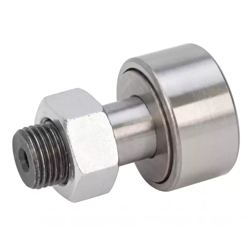
KR40 cam follower M18 stud
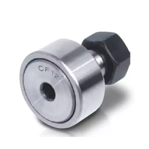
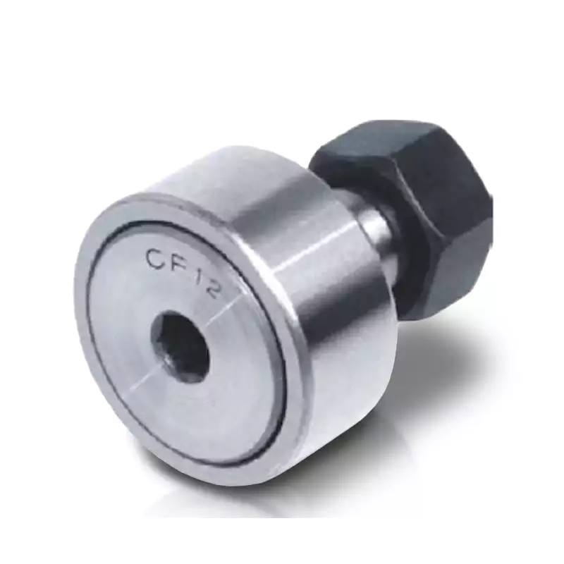
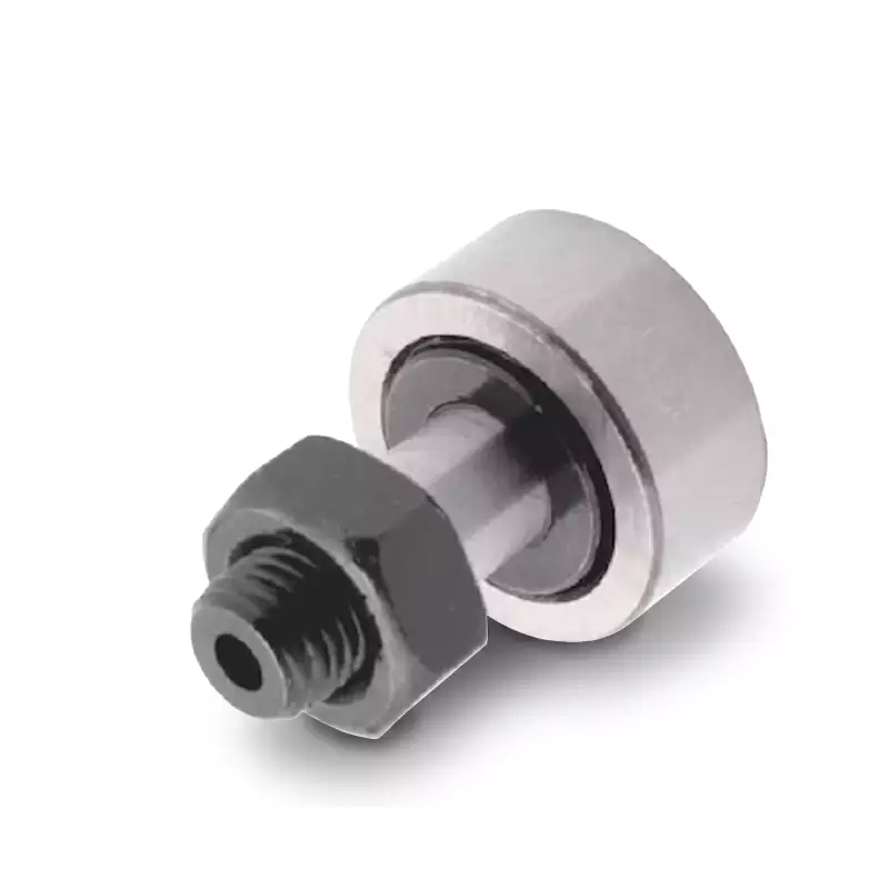
EP-KR40 stud type cam follower bearing with 40 mm outside diameter, M18 x 1.5 metric stud thread and CF18 cross-reference designation.
EP-KR40 combines a 40 mm outside diameter with a 20 mm roller width and M18 x 1.5 stud. Its CF18 reference provides a search path, while the dimension set separates it cleanly from KR35 and KR47.
The table gives B1 max = 58.2 mm and B2 = 36.5 mm, and the row mass is 247 g. The minimum corner radius entry also changes to 1 mm at this size, so the shoulder and surrounding geometry deserve attention during retrofit checks.
EP-KR40 is listed with D = 40 mm, C = 20 mm, stud diameter 18 mm and M18 x 1.5 thread. The legacy WERB references shown for this row are NAKD40 and NAKD40V.
Key Specifications
EP-KR40 uses the M18 x 1.5 stud interface shown above. Its C and C0 entries remain in the rating table without an added load unit because that unit is not printed in the project size table.
Full Dimension Table
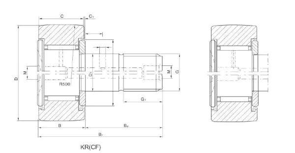
Use the drawing for EP-KR40 to locate D, C, the stud diameter, thread and axial lengths before measuring the removed part. Those interfaces are the primary replacement checks; the cross-reference code should agree with the dimensions rather than override them.
The running-surface note for EP-KR40 allows cylindrical or spherical execution depending on design. Confirm which surface profile the machine requires before choosing between the KR and KRV routes.
| Model | D* (mm) | C (mm) | d1 stud (mm) | Thread | G1 (mm) | B max (mm) | B1 max (mm) | B2 (mm) | B3 (mm) | C1 (mm) | rs min (mm) |
|---|---|---|---|---|---|---|---|---|---|---|---|
| EP-KR40 | 40 | 20 | 18 | M18 x 1.5 | 19 | 21.6 | 58.2 | 36.5 | 8 | 0.8 | 1.0 |
Rating and Cross-Reference Data
| Model | Eccentric e (mm)* | Dynamic C** | Static C0** | Limit speed (rpm) | Mass (g) | WERB old | WERB V old | IKO reference |
|---|---|---|---|---|---|---|---|---|
| EP-KR40 | 0.35 | 1180 | 1220 | 8500 | 247 | NAKD40 | NAKD40V | CF18 |
Eccentric value e = 0.35 mm belongs to the related KRE/KRVE execution for EP-KR40. The C/C0 columns are reproduced without a unit because none is printed in the table; confirm the unit convention before calculation.
Selection and Replacement Notes
Use EP-KR40 and CF18 to locate the candidate row, then verify the dimensions that matter on this machine. For this size, thread M18 x 1.5, roller diameter and roller width should agree with the removed follower or drawing before running-surface and lubrication details are reviewed.
Inspect the contact band while EP-KR40 is still in the mechanism if access allows. A centred, even band supports the size check; edge polishing or grooving is a reason to examine the rail, bracket and stud alignment instead of assuming a new follower alone will resolve the wear.
Forty-Millimetre Roller and M18 Thread Interface
For KR40, measure three items before comparing any cross-reference: D = 40 mm, C = 20 mm and the M18 x 1.5 thread. These dimensions place the follower between the M16-based KR35 and the M20-based KR47. That progression makes the stud diameter a strong check when the outer ring is dirty or difficult to access.
The listed B3 dimension is 8 mm and rs min is 1 mm. Those details matter when a machine drawing controls the shoulder, relief or available axial space around the stud. A replacement that matches roller diameter but conflicts with a shoulder radius can create an installation problem before the machine ever reaches operating load.
The rating row lists an 8,500 rpm limit-speed figure and e = 0.35 mm for the eccentric execution. In a cam-driven packaging or indexing station, record actual shaft/cam speed and how the follower is lubricated. The listed limit-speed figure is a selection reference; it does not replace a review of the real duty cycle.
Track wear becomes easier to see on this larger contact surface. Inspect for a polished path that is offset from the centre of the roller, and check that the mounting face is square. If the track is crowned, tapered or damaged, note that condition before choosing a cylindrical or spherical running-surface execution.
Applications for EP-KR40
Conveyor & material handling
Track-guided carriers, transfer stations and repeated material movement with accessible rail inspection.
Printing & packaging machinery
Cam-driven timing, folding, registration and transfer functions with medium-size follower envelopes.
Machine tools & production equipment
Indexing, guide and fixture mechanisms where rigid stud support and a clean contact band are important.
Indexing tables & cam drives
Repeated cam contact in machinery that cycles between defined positions.
Automation transfer systems
Larger transfer and fixture mechanisms that use stud-mounted rollers on a track.
General industrial track rollers
Rail-following mechanisms where D, C, thread and outer-surface profile are checked from a drawing or removed part.
EP-KR40 can appear in several industrial mechanisms, but the 40 mm running diameter and M18 x 1.5 stud are the useful first filters. Application-specific choices such as track profile and lubrication should be reviewed only after that interface is confirmed.
Related Products and Nearby Sizes
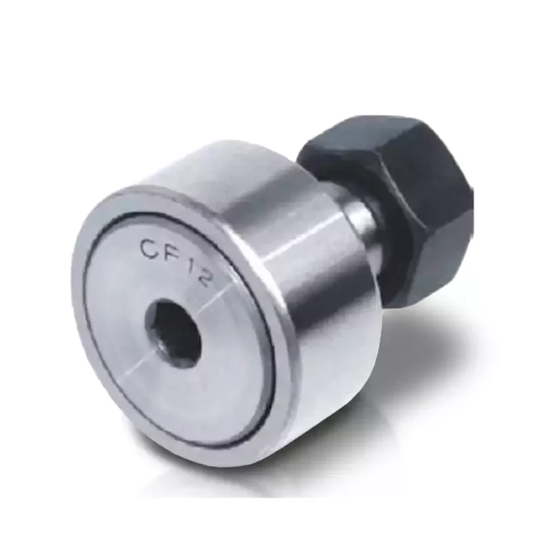
Use EP-KR35 and EP-KR47 as the lower and upper interface checks around EP-KR40. Both the stud diameter and roller width change on either side, so the nearby cards provide a quick sanity check against an uncertain old marking.
EP-KR35 Stud Type Cam Follower | CF16 Cross Reference
EP-KR35 stud type cam follower bearing with 35 mm outside diameter, M16 x 1.5 metric stud thread and CF16 cross-reference designation.
View specificationsEP-KR40 Cam Follower Bearing | CF18 Cross Reference | M18 Thread
EP-KR40 stud type cam follower bearing with 40 mm outside diameter, M18 x 1.5 metric stud thread and CF18 cross-reference designation.
View specificationsEP-KR47 Cam Follower Bearing | CF20 Cross Reference
EP-KR47 stud type cam follower bearing with 47 mm outside diameter, M20 x 1.5 metric stud thread and CF20 cross-reference designation.
View specificationsFAQ
What IKO reference is shown for EP-KR40?
The cross-reference table shows CF18 on the same size row as EP-KR40. Use that designation as a cross-reference search aid and verify D, C, stud thread, running-surface profile and any suffix-specific execution before replacement.
What thread does EP-KR40 use?
The listed stud thread for EP-KR40 is M18 x 1.5.
What is the related KRV or eccentric designation?
The paired KRV designation is EP-KRV40. If the machine is designed for eccentric adjustment, the naming convention for the corresponding eccentric executions is EP-KRE40 / EP-KRVE40; the table lists e = 0.35 mm for the size row.
What information should I send for a quote?
To review EP-KR40, send the CF18 or legacy reference, measured 40 mm D, 20 mm C, M18 x 1.5 thread, quantity, shoulder/mounting-face details and the operating speed of the cam or track if known.
Get a Quote for EP-KR40
For EP-KR40, a dimension sketch showing the M18 x 1.5 stud, 40 mm roller and mounting shoulder is more useful than a brand code by itself. Add a photo of the contact path when the machine shows uneven wear.