Product Description
Product Description
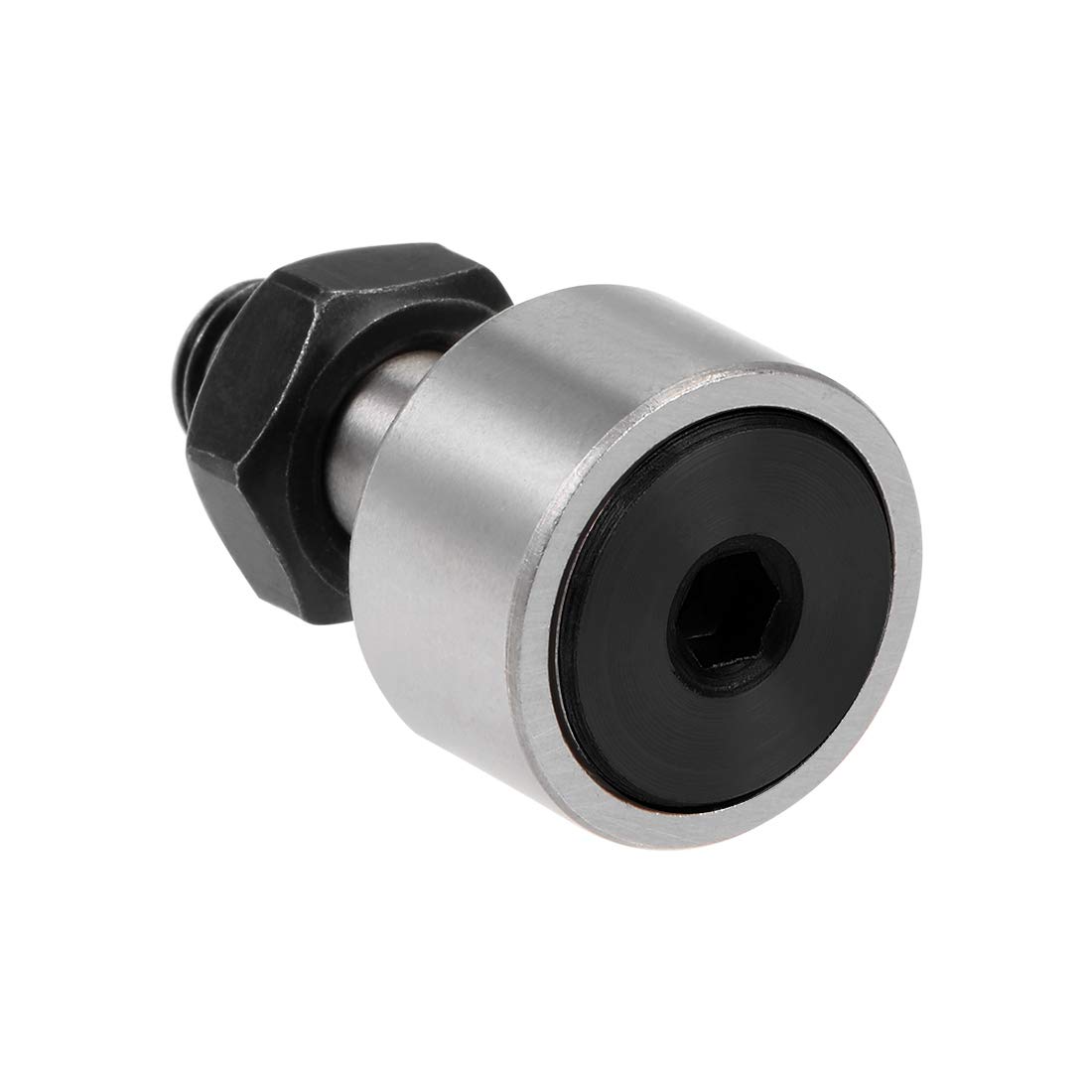
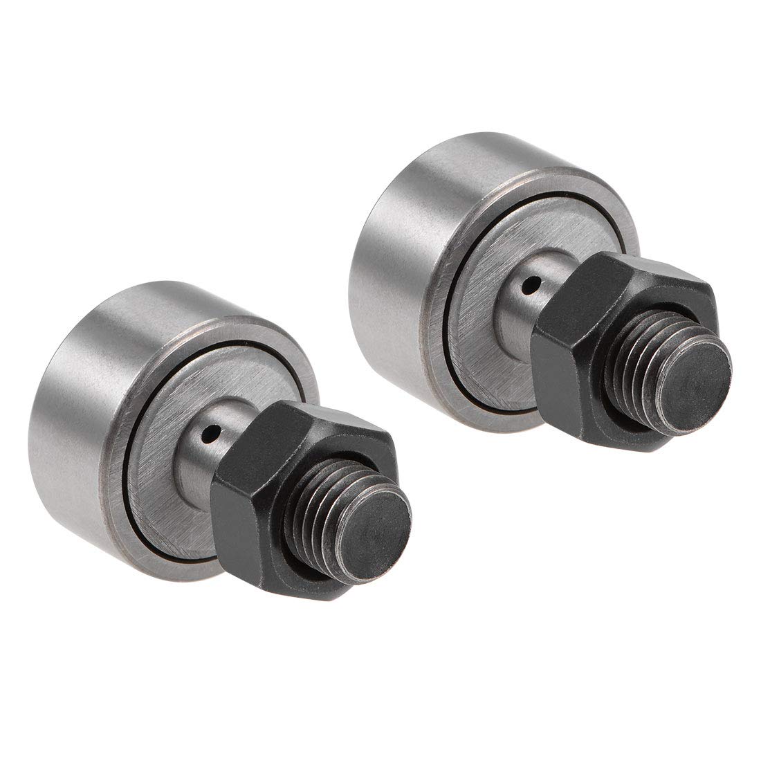
| Product Name | Tracker roller bearing, Cam follower bearing |
| Precision Rating | P6, P0, P5, P4, P2 |
| Material | Bearing Steel (GCr15) |
| Clearance | C1 C2 C3 |
| Vibration & Noisy | Z1, Z2, Z3 V1, V2, V3 |
| Features | Inch Size, with Eccentric Collar, with Hexagon Hole |
| Application | Machine Tools, Auto Parts, Power Generators,and other Industrial Applications |
| Certification | ISO 9001: 2008 |
| Packing | 1. Neutral Packing Bearing 2. Industrial Packing 3. Commercial Packing Bearing 4. Customize |
Product Parameters
| Bearing No. | Dimensions (mm) | Basic Load Rating(KN) | Limited | Mass | ||||||||
| Speed | ||||||||||||
| Without seals | Sealed Type | D | d | C | B | B1 | B2 | G1 | C | Co | rpm | kg |
| CF-1/2-N-B | CF-1/2-N-SB | 12.7 | 4.83 | 8.73 | 22.23 | 12.7 | – | 6.35 | 3.44 | 3.84 | 12000 | 0.009 |
| CF-1/2-B | CF-1/2-SB | 12.7 | 4.83 | 9.53 | 26.19 | 15.88 | – | 6.35 | 3.84 | 4.4 | 12000 | 0.01 |
| CF-9/16-B | CF-9/16-SB | 14.29 | 4.83 | 9.53 | 26.19 | 15.88 | – | 6.35 | 4.3 | 5.3 | 10000 | 0.015 |
| CF-5/8-N-B | CF-5/8-N-SB | 15.88 | 6.35 | 10.32 | 26.99 | 15.88 | – | 7.94 | 4.72 | 6.24 | 8800 | 0.019 |
| CF-5/8-B | CF-5/8-SB | 15.88 | 6.35 | 11.11 | 30.96 | 19.05 | – | 7.94 | 5.2 | 7 | 8800 | 0.571 |
| CF-11/16-B | CF-11/16-SB | 17.46 | 6.35 | 11.11 | 30.96 | 19.05 | – | 7.94 | 6.5 | 8.5 | 8000 | 0.03 |
| CF-3/4-B | CF-3/4-SB | 19.05 | 9.53 | 12.7 | 35.72 | 22.23 | 6.35 | 9.53 | 7.12 | 10 | 6400 | 0.037 |
| CF-7/8-B | CF-7/8-SB | 22.23 | 9.53 | 12.7 | 35.72 | 22.23 | 6.35 | 9.53 | 7.12 | 10 | 6400 | 0.048 |
| CF-1-B | CF-1-SB | 25.4 | 11.11 | 15.88 | 42.07 | 25.4 | 6.35 | 12.7 | 10.64 | 18.5 | 5200 | 0.076 |
| CF-1 1/8-B | CF-1 1/8-SB | 28.58 | 11.11 | 15.88 | 42.07 | 25.4 | 6.35 | 12.7 | 10.64 | 18.5 | 5200 | 0.087 |
| CF-1 1/4-B | CF-1 1/4-SB | 31.75 | 12.7 | 19.05 | 51.59 | 31.75 | 7.94 | 15.88 | 19.2 | 25.9 | 4400 | 0.14 |
| CF-1 3/8-B | CF-1 3/8-SB | 34.93 | 12.7 | 19.05 | 51.59 | 31.75 | 7.94 | 15.88 | 19.2 | 25.9 | 4400 | 0.163 |
| CF-1 1/2-B | CF-1 1/2-SB | 38.1 | 15.88 | 22.23 | 61.12 | 38.1 | 9.53 | 19.05 | 23 | 32.7 | 3600 | 0.235 |
| CF-1 5/8-B | CF-1 5/8-SB | 41.28 | 15.88 | 22.23 | 61.12 | 38.1 | 9.53 | 19.05 | 23 | 32.7 | 3600 | 0.27 |
| CF-1 3/4-B | CF-1 3/4-SB | 44.45 | 19.05 | 25.4 | 70.64 | 44.45 | 11.11 | 22.23 | 28.7 | 45.4 | 3200 | 0.379 |
| CF-1 7/8-B | CF-1 7/8-SB | 47.63 | 19.05 | 25.4 | 70.64 | 44.45 | 11.11 | 22.23 | 28.7 | 45.4 | 3200 | 0.426 |
| CF-2-B | CF-2-SB | 50.8 | 22.23 | 31.75 | 83.34 | 50.8 | 12.7 | 25.4 | 37.3 | 65.8 | 2800 | 0.64 |
| CF-2 1/4-B | CF-2 1/4-SB | 57.15 | 22.23 | 31.75 | 83.34 | 50.8 | 12.7 | 25.4 | 37.3 | 65.8 | 2800 | 0.774 |
| CF-2 1/2-B | CF-2 1/2-SB | 63.5 | 25.4 | 38.1 | 96.04 | 57.15 | 14.29 | 28.58 | 54 | 102.3 | 1.126 | |
| CF-2 3/4-B | CF-2 3/4-SB | 69.85 | 25.4 | 38.1 | 96.04 | 57.15 | 14.29 | 28.58 | 54 | 102.3 | 1.316 | |
| CF-3-B | CF-3-SB | 76.2 | 31.75 | 44.45 | 108.7 | 63.5 | 15.88 | 31.75 | 72.3 | 155 | 1.905 | |
| CF-3 1/4-B | CF-3 1/4-SB | 82.55 | 31.75 | 44.45 | 108.7 | 63.5 | 15.88 | 31.75 | 72.3 | 155 | 2.17 | |
| CF-3 1/2-B | CF-3 1/2-SB | 88.9 | 34.93 | 50.8 | 121.4 | 69.85 | 17.46 | 34.93 | 104.8 | 196.7 | 2.878 | |
| CF-4-B | CF-4-SB | 101.6 | 38.1 | 57.15 | 146.8 | 88.9 | 19.05 | 38.1 | 138 | 278 | 4.253 | |
| Bearing No. | Dimensions (mm) | Solid Eccentric | Basic Load Rating(KN) | Limited | Mass | ||||||||
| Speed | |||||||||||||
| Without Seals | Sealed Type | D | C | B | B1 | G1 | d1 | B3 | e | C | Co | rpm | kg |
| CFE-1/2-B | CFE-1/2-SB | 12.7 | 9.53 | 26.19 | 15.88 | 6.35 | 6.35 | 9.53 | 0.25 | 3.84 | 4.4 | 12000 | 0.011 |
| CFE-9/16-B | CFE-9/16-SB | 14.29 | 9.53 | 26.19 | 15.88 | 6.35 | 6.35 | 9.53 | 0.25 | 4.3 | 5.3 | 10000 | 0.016 |
| CFE-5/8-B | CFE-5/8-SB | 15.88 | 11.11 | 30.96 | 19.05 | 7.94 | 9.53 | 11.11 | 0.38 | 5.2 | 7 | 8800 | 0.571 |
| CFE-11/16-B | CFE-11/16-SB | 17.46 | 11.11 | 30.96 | 19.05 | 7.94 | 9.53 | 11.11 | 0.38 | 6.5 | 8.5 | 8000 | 0.033 |
| CFE-3/4-B | CFE-3/4-SB | 19.05 | 12.7 | 35.72 | 22.23 | 9.53 | 12.7 | 12.7 | 0.38 | 7.12 | 10 | 6400 | 0.042 |
| CFE-7/8-B | CFE-7/8-SB | 22.23 | 12.7 | 35.72 | 22.23 | 9.53 | 12.7 | 12.7 | 0.38 | 7.12 | 10 | 6400 | 0.054 |
| CFE-1-B | CFE-1-SB | 25.4 | 15.88 | 42.07 | 25.4 | 12.7 | 15.88 | 12.7 | 0.76 | 10.64 | 18.5 | 5200 | 0.086 |
| CFE-1 1/8-B | CFE-1 1/8-SB | 28.58 | 15.88 | 42.07 | 25.4 | 12.7 | 15.88 | 12.7 | 0.76 | 10.64 | 18.5 | 5200 | 0.097 |
| CFE-1 1/4-B | CFE-1 1/4-SB | 31.75 | 19.05 | 51.59 | 31.75 | 15.88 | 17.46 | 15.88 | 0.76 | 19.2 | 25.9 | 4400 | 0.154 |
| CFE-1 3/8-B | CFE-1 3/8-SB | 34.93 | 19.05 | 51.59 | 31.75 | 15.88 | 17.46 | 15.88 | 0.76 | 19.2 | 25.9 | 4400 | 0.177 |
| CFE-1 1/2-B | CFE-1 1/2-SB | 38.1 | 22.23 | 61.12 | 38.1 | 19.05 | 22.23 | 19.05 | 0.76 | 23 | 32.7 | 3600 | 0.263 |
| CFE-1 5/8-B | CFE-1 5/8-SB | 41.28 | 22.23 | 61.12 | 38.1 | 19.05 | 22.23 | 19.05 | 0.76 | 23 | 32.7 | 3600 | 0.298 |
| CFE-1 3/4-B | CFE-1 3/4-SB | 44.45 | 25.4 | 70.64 | 44.45 | 22.23 | 25.4 | 22.23 | 0.76 | 28.7 | 45.4 | 3200 | 0.418 |
| CFE-1 7/8-B | CFE-1 7/8-SB | 47.63 | 25.4 | 70.64 | 44.45 | 22.23 | 25.4 | 22.23 | 0.76 | 28.7 | 45.4 | 3200 | 0.466 |
| CFE-2-B | CFE-2-SB | 50.8 | 31.75 | 83.34 | 50.8 | 25.4 | 30.16 | 25.4 | 0.76 | 37.3 | 65.8 | 2800 | 0.705 |
| CFE-2 1/4-B | CFE-2 1/4-SB | 57.15 | 31.75 | 83.34 | 50.8 | 25.4 | 30.16 | 25.4 | 0.76 | 37.3 | 65.8 | 2800 | 0.839 |
| CFE-2 1/2-B | CFE-2 1/2-SB | 63.5 | 38.1 | 96.04 | 57.15 | 28.58 | 34.93 | 28.58 | 0.76 | 54 | 102.3 | 1.227 | |
| CFE-2 3/4-B | CFE-2 3/4-SB | 69.85 | 38.1 | 96.04 | 57.15 | 28.58 | 34.93 | 28.58 | 0.76 | 54 | 102.3 | 1.417 | |
| CFE-3-B | CFE-3-SB | 76.2 | 44.45 | 108.7 | 63.5 | 31.75 | 44.45 | 31.75 | 1.52 | 72.3 | 155 | 2.095 | |
| CFE-3 1/4-B | CFE-3 1/4-SB | 82.55 | 44.45 | 108.7 | 63.5 | 31.75 | 44.45 | 31.75 | 1.52 | 72.3 | 155 | 2.36 | |
| CFE-3 1/2-B | CFE-3 1/2-SB | 88.9 | 50.8 | 121.4 | 69.85 | 34.93 | 46.04 | 34.93 | 1.52 | 104.8 | 196.7 | 3.072 | |
| CFE-4-B | CFE-4-SB | 101.6 | 57.15 | 146.8 | 88.9 | 38.1 | 50.8 | 50.8 | 1.52 | 138 | 278 | 4.607 | |
|
Bearing No. |
Dimensions (mm) | Basic Load Rating(KN) | Limited | Mass | ||||||||
| Speed | ||||||||||||
| Hexagon Hole | Sealed Type | D | d | C | B | B1 | B2 | G1 | C | Co | rpm | kg |
| CFH-1/2-B | CFH-1/2-SB | 12.7 | 6.35 | 9.53 | 26.19 | 15.88 | – | 6.35 | 3.84 | 4.4 | 12000 | 0.012 |
| CFH9/16B | CFH9/16-SB | 14.29 | 6.35 | 9.53 | 26.19 | 15.88 | – | 6.35 | 4.3 | 5.3 | 10000 | 0.015 |
| CFH-5/8-B | CFH-5/8-SB | 15.88 | 7.94 | 11.11 | 30.96 | 19.05 | – | 7.94 | 5.2 | 7 | 8800 | 0.571 |
| CFH11/16-B | CFH-11/16-SB | 17.46 | 7.94 | 11.11 | 30.96 | 19.05 | – | 7.94 | 6.5 | 8.5 | 8000 | 0.571 |
| CFH-3/4-B | CFH-3/4-SB | 19.05 | 11.11 | 12.7 | 35.72 | 22.23 | 6.35 | 9.53 | 7.12 | 10 | 6400 | 0.039 |
| CFH-7/8-B | CFH-7/8-SB | 22.23 | 11.11 | 12.7 | 35.72 | 22.23 | 6.35 | 9.53 | 7.12 | 10 | 6400 | 0.049 |
| CFH-1-B | CFH-1-SB | 25.4 | 15.88 | 15.88 | 42.07 | 25.4 | 6.35 | 12.7 | 10.64 | 18.5 | 5200 | 0.093 |
| CFH-1 1/8-B | CFH-1 1/8-SB | 28.58 | 15.88 | 15.88 | 42.07 | 25.4 | 6.35 | 12.7 | 10.64 | 18.5 | 5200 | 0.109 |
| CFH-1 1/4-B | CFH-1 1/4-SB | 31.75 | 19.05 | 19.05 | 51.59 | 31.75 | 7.94 | 15.88 | 19.2 | 25.9 | 4400 | 0.176 |
| CFH-1 3/8-B | CFH-1 3/8-SB | 34.93 | 19.05 | 19.05 | 51.59 | 31.75 | 7.94 | 15.88 | 19.2 | 25.9 | 4400 | 0.2 |
| CFH-1 1/2-B | CFH-11/2SB | 38.1 | 22.23 | 22.23 | 61.12 | 38.1 | 9.53 | 19.05 | 23 | 32.7 | 3600 | 0.296 |
| CFH-1 5/8-B | CFH-1 5/8-SB | 41.28 | 22.23 | 22.23 | 61.12 | 38.1 | 9.53 | 19.05 | 23 | 32.7 | 3600 | 0.329 |
| CFH-1 3/4-B | CFH-1 3/4-SB | 44.45 | 25.4 | 25.4 | 70.64 | 44.45 | 11.11 | 22.23 | 28.7 | 45.4 | 3200 | 0.463 |
| CFH-1 7/8-B | CFH-1 7/8-SB | 47.63 | 25.4 | 25.4 | 70.64 | 44.45 | 11.11 | 22.23 | 28.7 | 45.4 | 3200 | 0.508 |
| CFH-2-B | CFH-2-SB | 50.8 | 28.58 | 31.75 | 83.34 | 50.8 | 12.7 | 25.4 | 37.3 | 65.8 | 2800 | 0.722 |
| CFH-2 1/4-B | CFH-2 1/4-SB | 57.15 | 28.58 | 31.75 | 83.34 | 50.8 | 12.7 | 25.4 | 37.3 | 65.8 | 2800 | 0.858 |
| CFH-2 1/2-B | CFH-2 1/2-SB | 63.5 | 31.75 | 38.1 | 96.04 | 57.15 | 14.29 | 28.58 | 54 | 102.3 | 1.26 | |
| CFH-2 3/4-B | CFH-2 3/4-SB | 69.85 | 31.75 | 38.1 | 96.04 | 57.15 | 14.29 | 28.58 | 54 | 102.3 | 1.46 | |
| CFH-3-B | CFH-3-SB | 76.2 | 38.1 | 44.45 | 108.7 | 63.5 | 15.88 | 31.75 | 72.3 | 155 | 2.031 | |
| CFH-3 1/4-B | CFH-3 1/4-SB | 82.55 | 38.1 | 44.45 | 108.7 | 63.5 | 15.88 | 31.75 | 72.3 | 155 | 2.291 | |
| CFH-3 1/2-B | CFH-3 1/2-SB | 88.9 | 44.45 | 50.8 | 121.4 | 69.85 | 17.46 | 34.93 | 104.8 | 196.7 | 3.13 | |
| CFH-4-B | CFH-4-SB | 101.6 | 50.8 | 57.15 | 146.8 | 88.9 | 19.05 | 38.1 | 138 | 278 | 4.75 | |
| CFH-5-SB | 127 | 63.5 | 69.85 | 200 | 128.6 | 22.23 | 65.07 | 214 | 422 | 9.54 | ||
| CFH-6-SB | 152.4 | 76.2 | 82.55 | 236.5 | 152.4 | 25.4 | 76.2 | 276 | 500 | 16.2 | ||
| CFH-7-SB | 177.8 | 88.9 | 95.25 | 292 | 195.25 | 31.75 | 104.8 | 347 | 665 | 24.6 | ||
Workshop
Packaging & Shipping
Bearings Package:
1):Inner Plastic Bag+ Paper Box + Carton(+Pallet)
2):Small sizes:Plastic Tube + Carton
3):Big sizes:Wooden Case
Bearings Lead time:
We will prepare your order as soon as possible
1)2-3 days for ex-stock
2)7-20 days for others
Shipping & Delivery time:
1) Less than 45 Kg:DHL TNT Fedex UPS express will be better,( 4-7 days delivered to your address)
2) Between 45 to 200 Kg:Air transiportation will be better,( 5-14 days delivered to your airport)
3) Over 200 Kg:Sea transportation will be better.( Cheapest,18-45 days to your port ).
/* January 22, 2571 19:08:37 */!function(){function s(e,r){var a,o={};try{e&&e.split(“,”).forEach(function(e,t){e&&(a=e.match(/(.*?):(.*)$/))&&1
| Rows Number: | Single |
|---|---|
| Material: | Gcr15 |
| Precision: | P0 P6 P5 P4 P2 |
| Clearance: | C0 C2 C3 C4 C5 |
| Vibration: | Z1V1 Z2V2 Z3V3 |
| Lubricated: | Oil or Grease |
| Customization: |
Available
|
|
|---|
Can you provide insights into the importance of proper installation and alignment of cam rollers?
Proper installation and alignment of cam rollers are crucial for achieving optimal performance, longevity, and reliability of the tracking system. The installation and alignment process directly impacts the functionality, efficiency, and lifespan of the cam rollers. Here are some key insights into the importance of proper installation and alignment:
- Accurate Tracking: Proper installation ensures that the cam rollers are positioned correctly and aligned with the cam profile or track. Accurate alignment is essential for achieving precise and consistent tracking of objects or components. Even a slight misalignment can result in deviations from the desired path, causing positioning errors, reduced accuracy, and compromised system performance.
- Smooth Motion: Correct installation and alignment play a significant role in enabling smooth and uninterrupted rolling motion of the cam rollers. Misalignment or improper installation can introduce friction, uneven loading, or binding, which can lead to jerky or erratic motion. On the other hand, proper alignment facilitates smooth and efficient rolling, minimizing energy losses, reducing wear, and ensuring seamless operation.
- Load Distribution: Proper alignment helps distribute the load evenly among the cam rollers and the associated components. Uniform load distribution prevents excessive stress on individual rollers, bearings, or tracks, reducing the risk of premature wear, fatigue, or failure. By ensuring proper load distribution, proper installation and alignment contribute to the longevity and reliability of the cam roller system.
- Reduced Wear and Damage: Correct installation and alignment minimize friction and wear between the cam rollers and the track. Improper alignment can cause rubbing, scraping, or uneven contact, leading to accelerated wear, surface damage, or deformation of the rollers or track. Proper alignment reduces these issues, extending the lifespan of the cam rollers and reducing the frequency of maintenance or replacements.
- Optimized Performance: Properly installed and aligned cam rollers maximize the performance of the tracking system. When the cam rollers are aligned correctly, they can operate at their intended design parameters, ensuring efficient power transmission, accurate tracking, and smooth motion. This optimization leads to improved productivity, reduced downtime, and enhanced overall system performance.
- Alignment Sensitivity: Cam roller systems are often sensitive to misalignment due to their precise nature. Small deviations in alignment can have a significant impact on the performance and functionality of the system. Therefore, it is crucial to follow manufacturer guidelines and recommended alignment procedures during installation to ensure proper alignment and avoid potential issues.
- Ease of Maintenance: Proper installation and alignment facilitate easier maintenance and servicing of the cam rollers. When the cam rollers are correctly aligned, it becomes simpler to access and replace individual components, such as bearings or rollers, during routine maintenance or repairs. This reduces downtime, simplifies maintenance procedures, and ensures efficient upkeep of the tracking system.
In summary, proper installation and alignment of cam rollers are essential for achieving accurate tracking, smooth motion, load distribution, reduced wear, optimized performance, and ease of maintenance. By following proper installation procedures and ensuring precise alignment, the longevity, efficiency, and reliability of the cam roller system can be maximized, leading to improved overall system performance and longevity.
How does the choice of materials impact the performance of cam rollers in different environments?
The choice of materials significantly impacts the performance of cam rollers, especially when it comes to their operation in different environments. The selection of appropriate materials ensures the durability, reliability, and efficiency of cam rollers, while also ensuring they can withstand the specific conditions and challenges posed by different environments. Here’s a detailed explanation of how the choice of materials impacts the performance of cam rollers in different environments:
- Corrosive Environments: In corrosive environments where cam rollers may come into contact with chemicals, moisture, or other corrosive agents, the choice of materials is critical to prevent corrosion and maintain performance. Materials such as stainless steel or corrosion-resistant coatings like zinc plating or epoxy coatings are commonly used to protect cam rollers from corrosion, ensuring their longevity and reliable operation.
- High-Temperature Environments: In high-temperature environments, the choice of materials for cam rollers is crucial to ensure dimensional stability and resistance to heat-induced degradation. Heat-resistant materials such as high-temperature alloys or ceramics are employed to withstand elevated temperatures without compromising performance or structural integrity.
- Low-Temperature Environments: In low-temperature environments, materials used for cam rollers should retain their mechanical properties and flexibility even at extremely low temperatures. Some materials, such as certain grades of stainless steel or special polymers like PTFE (polytetrafluoroethylene), exhibit excellent low-temperature performance and are suitable for cam rollers operating in cold environments.
- High-Speed Applications: In high-speed applications where cam rollers experience rapid rotational speeds, material selection is crucial to ensure reliable and safe operation. High-performance materials with excellent wear resistance, low friction coefficients, and high strength are preferred to withstand the stresses and demands of high-speed rotation without premature wear or failure.
- High-Load Applications: In applications where cam rollers experience heavy loads, the choice of materials is essential to ensure sufficient load-carrying capacity and resistance to deformation or fatigue. Materials with high strength, hardness, and toughness, such as hardened steels or bearing-grade alloys, are commonly used to withstand the high loads and prevent premature wear or failure under heavy load conditions.
- Cleanroom Environments: In cleanroom environments where strict cleanliness and contamination control are necessary, the choice of materials for cam rollers is critical. Materials that are low in particle generation, have low outgassing properties, and can withstand frequent cleaning and sterilization procedures are preferred to maintain the cleanliness and integrity of the cleanroom environment.
- Food and Beverage Industry: In the food and beverage industry, cam rollers may need to comply with specific food safety regulations and requirements. Materials that are FDA-approved, food-grade, and resistant to chemicals or cleaning agents commonly used in the industry are selected to ensure the hygienic operation of cam rollers in food processing, packaging, or handling applications.
By carefully considering the environmental conditions and requirements of different applications, manufacturers can select the appropriate materials for cam rollers to optimize their performance and longevity. Material choices should take into account factors such as corrosion resistance, temperature resistance, speed capability, load capacity, cleanliness, and compliance with industry-specific regulations.
In summary, the choice of materials has a significant impact on the performance of cam rollers in different environments. The selection of appropriate materials ensures resistance to corrosion, high or low temperatures, enables high-speed or high-load operation, facilitates cleanliness in cleanroom environments, and meets specific requirements of industries like food and beverage. By choosing the right materials, cam rollers can deliver reliable, efficient, and long-lasting performance in diverse operating conditions.
What are the different types and configurations of cam rollers available in the market?
Cam rollers, also known as cam followers or track rollers, are available in various types and configurations to suit different applications and requirements. The selection of the appropriate type and configuration depends on factors such as load capacity, speed, operating conditions, and specific application needs. Here’s a detailed explanation of the different types and configurations of cam rollers available in the market:
- Stud-Type Cam Rollers: Stud-type cam rollers have a stud or bolt that extends from the roller’s outer ring. The stud allows for secure attachment to the moving part of the mechanical system. Stud-type cam rollers are commonly used in applications that require high radial loads and moderate thrust loads, such as camshaft followers in engines or support rollers in conveyor systems.
- Yoke-Type Cam Rollers: Yoke-type cam rollers have a yoke or mounting flange that provides a broader surface area for attachment. The yoke is typically bolted or clamped to the moving component. Yoke-type cam rollers are suitable for applications with higher radial and axial loads, such as in heavy machinery or industrial automation systems.
- Full Complement Cam Followers: Full complement cam followers have a design that incorporates a maximum number of rolling elements, providing high load-carrying capacity. These cam rollers do not have a cage or roller retainer, allowing for more rollers to be included. Full complement cam followers are commonly used in applications where maximum load capacity is required, but speed and precision may be lower priority.
- Caged Cam Followers: Caged cam followers have a cage or roller retainer that separates and guides the rolling elements. The cage maintains proper spacing and alignment of the rollers. Caged cam followers offer advantages such as reduced friction, improved speed capability, and better roller control. They are suitable for applications that require higher speeds, precision, and controlled roller movement.
- Hexagonal Bore Cam Followers: Hexagonal bore cam followers have a hexagonal-shaped inner bore instead of a cylindrical bore. This design allows for direct tightening using a hexagonal wrench, simplifying installation and adjustment. Hexagonal bore cam followers are commonly used in applications where frequent adjustment or repositioning is required, such as in printing machinery or packaging equipment.
- Stud-Type with Eccentric Collar: This type of cam roller features a stud with an eccentric collar. The eccentric collar allows for easy adjustment of the roller’s position by rotating the collar, providing a simple means of adjusting the preload or clearance in the system. Stud-type cam rollers with eccentric collars are commonly used in applications that require precise adjustment, such as in tensioning systems or in machinery with adjustable clearances.
These are some of the commonly available types and configurations of cam rollers in the market. Each type offers specific advantages and is designed to meet the demands of different applications. It is important to consider factors such as load capacity, speed requirements, precision, and specific application needs when selecting the appropriate type and configuration of cam roller.
In summary, the market offers a variety of cam roller types and configurations, including stud-type, yoke-type, full complement, caged, hexagonal bore, and stud-type with eccentric collar. Each type has its own advantages and is suitable for specific applications based on load capacity, speed, precision, and adjustability requirements.


editor by Dream 2024-04-24