Product Description
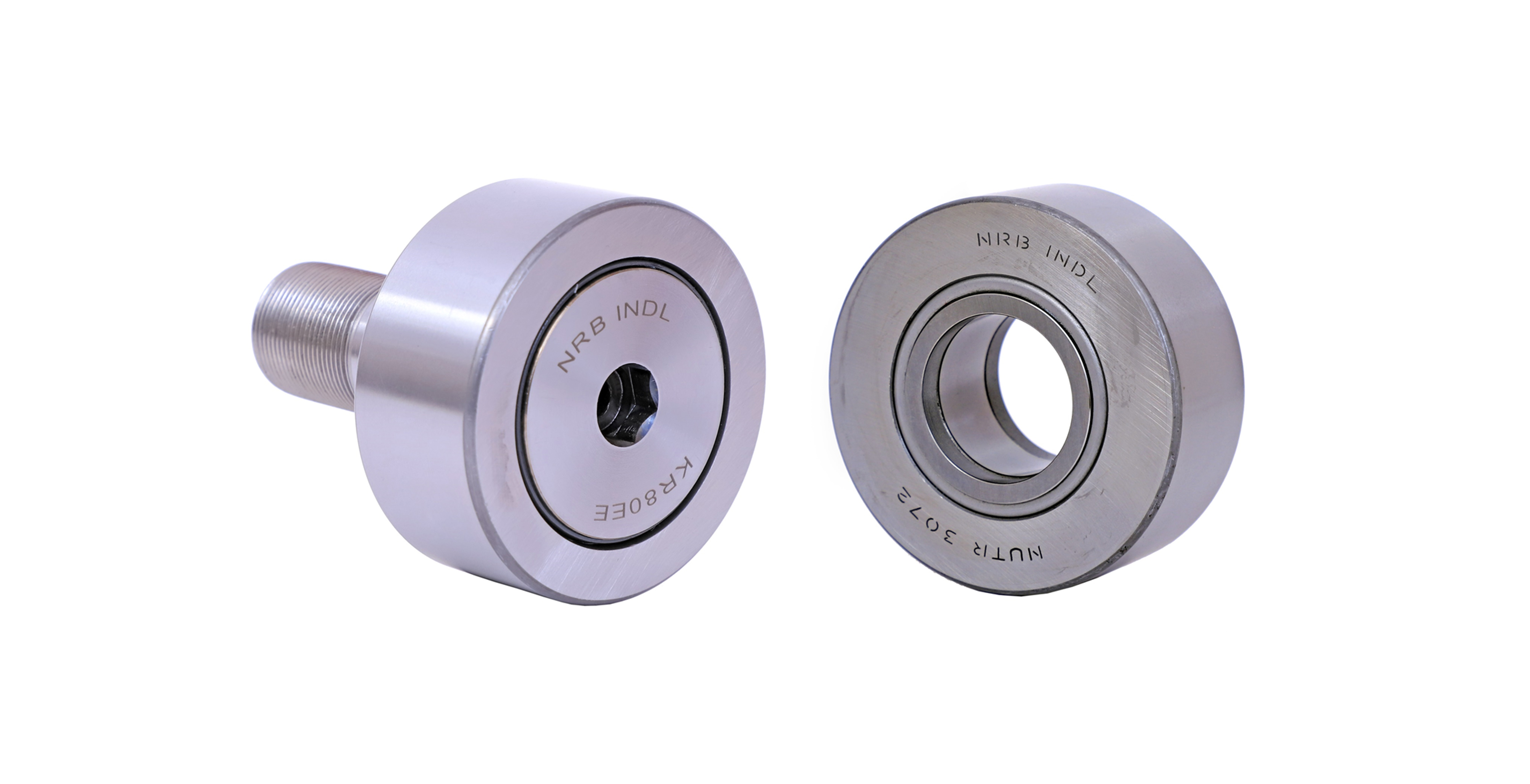
CF 10 BR / CF 10 BUUR Stud Type Track Rollers for engine
Application
Metals Mining, Mineral Processing and Cement
Railways Industrial Applications.
Material Handling Agriculture
Construction Machine Tools
Auto Parts Power Generators
Cam Followers Stud-Type Track Rollers are designed to run on all types of tracks and to be used in cam drives, conveyor systems,
etc.They are based on either needle or cylindrical roller bearings. Instead of an inner ring, they have a threaded CHINAMFG stud (pin)
CF..BR/CF..BUUR Stud Type Track Rollers Specification
| Product Name | CF..BR/CF..BUUR Stud Type Track Rollers |
| Precision Rating | P6, P0, P5, P4, P2 |
| Material | Bearing Steel (GCr15) |
| Clearance | C0 C1 C2 C3 C4 C5 |
| Vibration & Noisy | Z1, Z2, Z3 V1, V2, V3 |
| Features | With Axial Guidance, Axial Plain Washers on Both Sides |
| CF..BR Features | Shiled Type |
| CF..BUUR Features | Sealed Type |
| Application | Machine Tools, Auto Parts, Power Generators,and other Industrial Applications |
| Certification | ISO 9001: 2008 |
| Packing | 1. Neutral Packing Bearing 2. Industrial Packing 3. Commercial Packing Bearing 4. Customize |
| Delivery Time | 30 – 45 Days After The Order is Confirmed |
| Shippment | 1. By Sea 2. By Air 3. By Express |
| Model | Dimensions (mm) | Basic Load Rating (KN) |
Limited | Mass | ||||||||||||||
| Speed | ||||||||||||||||||
| Shiled Type | Seale Type | D | d | C | r | B | B1 | B2 | G | G1 | A/F | M1 | C1 | B3 | C | Co | rpm | kg |
| min | max | max | ||||||||||||||||
| CF 6 BR | CF 6 BUUR | 16 | 6 | 11 | 0.3 | 12.2 | 28.2 | 16 | M6X1 | 8 | 3 | – | 0.6 | – | 2.96 | 2.96 | 17600 | 0.019 |
| CF 8 BR | CF 8 BUUR | 19 | 8 | 11 | 0.3 | 12.2 | 32.2 | 20 | M8X1.25 | 10 | 4 | – | 0.6 | – | 3.44 | 3.84 | 13600 | 0.571 |
| CF 10 BR | CF 10 BUUR | 22 | 10 | 12 | 0.3 | 13.2 | 36.2 | 23 | M10X1.25 | 12 | 4 | – | 0.6 | – | 4.4 | 5.6 | 11200 | 0.045 |
| CF 10-1 BR | CF 10-1 BUUR | 26 | 10 | 12 | 0.3 | 13.2 | 36.2 | 23 | M10X1.25 | 12 | 4 | – | 0.6 | – | 4.4 | 5.6 | 11200 | 0.06 |
| CF 12 BR | CF 10 BUUR | 30 | 12 | 14 | 0.6 | 15.2 | 40.2 | 25 | M12X1.5 | 13 | 6 | 6 | 0.6 | 6 | 6.48 | 8 | 8800 | 0.095 |
| CF 12-1 BR | CF 12-1 BUUR | 32 | 12 | 14 | 0.6 | 15.2 | 40.2 | 25 | M12X1.5 | 13 | 6 | 6 | 0.6 | 6 | 6.48 | 8 | 8800 | 0.105 |
| CF 16 BR | CF 16 BUUR | 35 | 16 | 18 | 0.6 | 19.6 | 52.1 | 32.5 | M16X1.5 | 17 | 6 | 6 | 0.8 | 8 | 9.84 | 14.96 | 6800 | 0.17 |
| CF 18 BR | CF 18 BUUR | 40 | 18 | 20 | 1 | 21.6 | 58.1 | 36.5 | M18X1.5 | 19 | 8 | 6 | 0.8 | 8 | 12 | 20.56 | 5600 | 0.25 |
| CF 20-1 BR | CF 20-1 BUUR | 47 | 20 | 24 | 1 | 25.6 | 66.1 | 40.5 | M20X1.5 | 21 | 8 | 8 | 0.8 | 9 | 16.88 | 28.24 | 5200 | 0.385 |
| CF 20 BR | CF 20 BUUR | 52 | 20 | 24 | 1 | 25.6 | 66.1 | 40.5 | M20X1.5 | 21 | 8 | 8 | 0.8 | 9 | 16.88 | 28.24 | 5200 | 0.46 |
| CF 24 BR | CF 24 BUUR | 62 | 24 | 29 | 1 | 30.6 | 80.1 | 49.5 | M24X1.5 | 25 | 12 | 8 | 0.8 | 11 | 24.88 | 42.96 | 4400 | 0.815 |
| CF 24-1 BR | CF 24-1 BUUR | 72 | 24 | 29 | 1 | 30.6 | 80.1 | 49.5 | M24X1.5 | 25 | 12 | 8 | 0.8 | 11 | 24.88 | 42.96 | 4400 | 1.14 |
| CF 30 BR | CF 30 BUUR | 80 | 30 | 35 | 1 | 37 | 100 | 63 | M30X1.5 | 32 | 17 | 8 | 1 | 15 | 37.04 | 69.44 | 3200 | 1.87 |
| CF 30-1 BR | CF 30-1 BUUR | 85 | 30 | 35 | 1 | 37 | 100 | 63 | M30X1.5 | 32 | 17 | 8 | 1 | 15 | 37.04 | 69.44 | 3200 | 2.03 |
| CF 30-2 BR | CF 30-2 BUUR | 90 | 30 | 35 | 1 | 37 | 100 | 63 | M30X1.5 | 32 | 17 | 8 | 1 | 15 | 37.04 | 69.44 | 3200 | 2.22 |
CF..VBR / CF..VBUUR Specification
| Model | Dimensions (mm) | Basic Load Rating (KN) |
Limited | Mass | ||||||||||||||
| Speed | ||||||||||||||||||
| Shield Type | Sealed Type | D | d | C | r | B | B1 | B2 | G | G1 | A/F | M1 | C1 | B3 | C | Co | rpm | kg |
| min | max | max | ||||||||||||||||
| CF 6 VBR | CF 6 VBUUR | 16 | 6 | 11 | 0.3 | 12.2 | 28.2 | 16 | M6X1 | 8 | 3 | 0.6 | 5.68 | 6.96 | 9600 | 0.019 | ||
| CF 8 VBR | CF 8 VBUUR | 19 | 8 | 11 | 0.3 | 12.2 | 32.2 | 20 | M8X1.25 | 10 | 4 | 0.6 | 6.64 | 9.12 | 7200 | 0.571 | ||
| CF 10 VBR | CF 10 VBUUR | 22 | 10 | 12 | 0.3 | 13.2 | 36.2 | 23 | M10X1.25 | 12 | 4 | 0.6 | 7.76 | 11.84 | 5600 | 0.046 | ||
| CF10-1 VBR | CF10-1VBUUR | 26 | 10 | 12 | 0.3 | 13.2 | 36.2 | 23 | M10X1.25 | 12 | 4 | 0.6 | 7.76 | 11.84 | 5600 | 0.061 | ||
| CF 12 VBR | CF 12 VBUUR | 30 | 12 | 14 | 0.6 | 15.2 | 40.2 | 25 | M12X1.5 | 13 | 6 | 6 | 0.6 | 6 | 10.96 | 16.08 | 4800 | 0.097 |
| CF12-1 VBR | CF12-1VBUUR | 32 | 12 | 14 | 0.6 | 15.2 | 40.2 | 25 | M12X1.5 | 13 | 6 | 6 | 0.6 | 6 | 10.96 | 16.08 | 4800 | 0.107 |
| CF 16 VBR | CF 16 VBUUR | 35 | 16 | 18 | 0.6 | 19.6 | 52.1 | 32.5 | M16X1.5 | 17 | 6 | 6 | 0.8 | 8 | 16.88 | 30.72 | 3600 | 0.173 |
| CF 18 VBR | CF 18 VBUUR | 40 | 18 | 20 | 1 | 21.6 | 58.1 | 36.5 | M18X1.5 | 19 | 8 | 6 | 0.8 | 8 | 20.64 | 41.92 | 2800 | 0.255 |
| CF20-1 VBR | CF20-1VBUUR | 47 | 20 | 24 | 1 | 25.6 | 66.1 | 40.5 | M20X1.5 | 21 | 8 | 8 | 0.8 | 9 | 27.04 | 52.64 | 2800 | 0.39 |
| CF 20 VBR | CF 20 VBUUR | 52 | 20 | 24 | 1 | 25.6 | 66.1 | 40.5 | M20X1.5 | 21 | 8 | 8 | 0.8 | 9 | 27.04 | 52.64 | 2800 | 0.465 |
| CF 24 VBR | CF 24 VBUUR | 62 | 24 | 29 | 1 | 30.6 | 80.1 | 49.5 | M24X1.5 | 25 | 12 | 8 | 0.8 | 11 | 38 | 75.12 | 2400 | 0.82 |
| CF24-1 VBR | CF24-1VBUUR | 72 | 24 | 29 | 1 | 30.6 | 80.1 | 49.5 | M24X1.5 | 25 | 12 | 8 | 0.8 | 11 | 38 | 75.12 | 2400 | 1.14 |
| CF 30 VBR | CF 30 VBUUR | 80 | 30 | 35 | 1 | 37 | 100 | 63 | M30X1.5 | 32 | 17 | 8 | 1 | 15 | 55.2 | 60.08 | 1600 | 1.87 |
| CF30-1 VBR | CF30-1VBUUR | 85 | 30 | 35 | 1 | 37 | 100 | 63 | M30X1.5 | 32 | 17 | 8 | 1 | 15 | 55.2 | 60.08 | 1600 | 2.03 |
| CF30-2 VBR | CF30-2VBUUR | 90 | 30 | 35 | 1 | 37 | 100 | 63 | M30X1.5 | 32 | 17 | 8 | 1 | 15 | 55.2 | 60.08 | 1600 | 2.22 |
About Us
HENGLI Machinery Company is a well-established Chinese bearing supplier. We design, manufacture and wholesale bearings.
Our specialized manufacturer of Spherical Roller Bearing & Cylindrical Roller Bearing, XIHU (WEST LAKE) DIS. Rolling Bearing Co., Ltd was
established in 1970 and is accredited by the Chinese Ministry of Machine Building.
We invested in 2 additional specialized bearing factories, which allow us to provide our clients with top of the line products
such as Needle Roller Bearings, Cam Follower Bearings, Thrust Bearings, Spherical Plain Bearings, Rod Ends Bearings,
Ball Joint Bearings,Tapered Roller Bearings, Wheel Hub Bearings and Non-Standard Bearings.
FAQ
Q1 – What is our advantages?
A – Manufacturer – Do it only with the Best;
-Your Choice make different.
Q2 – Our Products
A – Spherical Roller Bearing, Cylindrical Roller Bearing, Needle Roller Bearing, Cam Followers, Thrust Bearing
– Spherical Plain Bearing, Rod End, Ball Joint, Wheel Hub, Tapered Roller Bearing
Q3 – Process of our production
A – Heat Treatment – Grinding – Parts Inspection – Assembly – Final Inspection – Packing
Q4 – How to customize bearing(non-standard) from your company?
A -We offer OEM, Customized(Non-standard) service and you need to provide drawing and detailed Technical Data.
Q5 – What should I care before installation?
A – Normally, the preservative with which new bearings are coated before leaving the factory does not need to be
Removed; It is only necessary to wipe off the outside cylindrical surface and bore, if the grease is not compatible
With the preservative, it is necessary to wash and carefully dry the bearing.
-Bearings should be installed in a dry, dust-free room away from metal working or other machines producing
Swarf and dust.
Q6 – How to stock and maintenance my bearings right?
A – Do not store bearings directly on concrete floors, where water can condense and collect on the bearing;
-Store the bearings on a pallet or shelf, in an area where the bearings will not be subjected to high humidity
Or sudden and severe temperature changes that may result in condensation forming;
-Always put oiled paper or, if not available, plastic sheets between rollers and cup races of tapered roller bearings.
/* May 10, 2571 16:49:51 */!function(){function d(e,r){var a,o={};try{e&&e.split(“,”).forEach(function(e,t){e&&(a=e.match(/(.*?):(.*)$/))&&1
How do electronic or computer-controlled components integrate with cam rollers in modern applications?
In modern applications, electronic or computer-controlled components play a significant role in integrating with cam rollers to enhance functionality, precision, and automation. The integration of electronic or computer-controlled components with cam rollers enables advanced control, monitoring, and synchronization of the motion system. Here’s a detailed explanation of how electronic or computer-controlled components integrate with cam rollers in modern applications:
- Sensor Integration: Electronic sensors can be integrated with cam rollers to provide real-time feedback on various parameters such as position, speed, acceleration, and load. Position sensors, such as encoders or linear displacement sensors, can be used to precisely determine the position of the cam rollers and the objects or components they are tracking. This information can then be used for closed-loop control, ensuring accurate tracking and motion control.
- Control Systems: Electronic or computer-controlled systems can be employed to manage the operation of cam rollers. These control systems can receive input from sensors and use algorithms to calculate the desired motion profiles. They can then generate signals to drive motors or actuators that control the movement of the cam rollers. By integrating control systems, precise motion control, synchronization, and programmability can be achieved, enabling complex motion sequences and adaptive tracking capabilities.
- Communication Protocols: Electronic or computer-controlled components can utilize various communication protocols to exchange data and commands with other system components. For example, in industrial automation applications, cam rollers may be integrated into a larger control network using protocols such as Modbus, CAN bus, or Ethernet. This integration enables seamless communication, coordination, and synchronization with other components or systems, enhancing overall system performance and functionality.
- Human-Machine Interface (HMI): In applications where human interaction is involved, electronic or computer-controlled components can provide a user interface for monitoring and controlling the cam rollers. This interface can include touch screens, graphical displays, or control panels that allow operators to set parameters, monitor performance, and adjust settings as needed. The integration of HMIs with cam rollers simplifies operation, facilitates troubleshooting, and enhances user experience.
- Data Logging and Analysis: Electronic or computer-controlled components can capture and log data related to the operation of cam rollers and the overall tracking system. This data can include parameters such as position, speed, acceleration, forces, and system status. By analyzing this data, performance trends, anomalies, and optimization opportunities can be identified. The integration of data logging and analysis capabilities enables proactive maintenance, performance optimization, and continuous improvement of the cam roller system.
- Integration with Automation Systems: In automated systems, electronic or computer-controlled components can integrate cam rollers into the overall automation framework. This integration allows for seamless coordination with other automated processes, robotics, or material handling systems. By integrating cam rollers with automation systems, precise tracking, synchronized motion, and efficient production workflows can be achieved.
The integration of electronic or computer-controlled components with cam rollers brings advanced capabilities to modern applications. It enables precise control, adaptive tracking, real-time monitoring, data-driven optimization, and seamless integration with automation systems. This integration enhances the functionality, flexibility, and efficiency of cam roller systems, opening up possibilities for a wide range of applications in industries such as manufacturing, robotics, packaging, material handling, and more.
What maintenance practices are recommended for cam rollers to ensure optimal functionality?
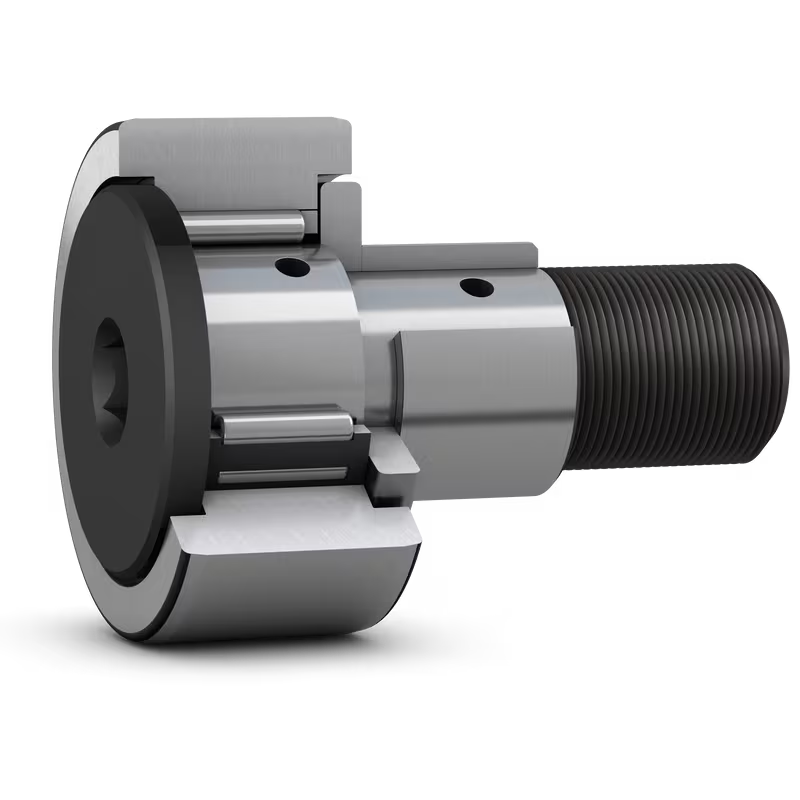
Proper maintenance is essential for ensuring the optimal functionality and longevity of cam rollers. Regular maintenance practices help prevent premature wear, minimize downtime, and maintain the performance of cam rollers in various applications. Here are some recommended maintenance practices for cam rollers:
- Cleaning: Regularly clean the cam rollers to remove dust, dirt, and debris that can accumulate on the rolling surfaces. Use a soft brush or compressed air to clean the cam rollers, ensuring that no contaminants hinder their smooth operation.
- Lubrication: Apply appropriate lubrication to the cam rollers to reduce friction and wear. Use lubricants recommended by the manufacturer, ensuring they are compatible with the materials and operating conditions of the cam rollers. Regularly check the lubrication levels and replenish as needed.
- Inspection: Perform routine visual inspections of the cam rollers to check for any signs of wear, damage, or misalignment. Look for excessive play, deformation, or any irregularities that may affect their performance. If any issues are identified, take appropriate measures such as adjustments, repairs, or replacements.
- Tightening: Check the fasteners, such as bolts or screws, that secure the cam rollers to the equipment or mounting surfaces. Ensure that they are properly tightened to prevent loosening during operation, which could lead to misalignment or reduced performance.
- Alignment: Check the alignment of the cam rollers periodically to ensure they are properly aligned with the cam or track they are following. Misalignment can lead to increased wear, reduced accuracy, and decreased lifespan of the cam rollers. Adjust the alignment as necessary to maintain optimal functionality.
- Load Distribution: Monitor the load distribution among the rolling elements of the cam rollers. Ensure that the load is evenly distributed to prevent overloading or excessive stress on individual rolling elements. Uneven load distribution can lead to premature wear or failure of the cam rollers.
- Environmental Considerations: Consider the specific environmental conditions in which the cam rollers operate. Take appropriate measures to protect the cam rollers from corrosive substances, extreme temperatures, excessive moisture, or other environmental factors that may affect their performance. Use protective coatings, seals, or covers as needed.
- Replacement: Cam rollers have a finite lifespan, and eventually, they will need to be replaced. Monitor the wear and performance of the cam rollers over time. When signs of significant wear, damage, or reduced functionality are observed, plan for timely replacement to avoid unexpected failures or disruptions in the operation.
It is important to note that maintenance practices may vary depending on the specific design, materials, and operating conditions of the cam rollers. Therefore, it is recommended to refer to the manufacturer’s guidelines and recommendations for maintenance specific to the cam rollers being used.
By following these maintenance practices and adopting a preventive maintenance approach, operators can ensure the optimal functionality, reliability, and longevity of cam rollers in various applications.
How does the design of a cam roller contribute to efficient motion and tracking?
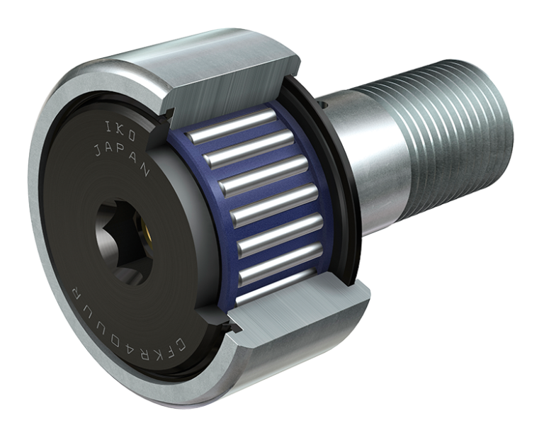
The design of a cam roller plays a crucial role in ensuring efficient motion transmission and tracking along the surface profile of a cam or track. Various design features are incorporated to optimize performance, reliability, and smooth operation. Here’s a detailed explanation of how the design of a cam roller contributes to efficient motion and tracking:
- Bearing Element: The choice of the bearing element, such as cylindrical rollers, needle rollers, or ball bearings, is a critical design consideration. The bearing element should be selected based on the specific application requirements, including load capacity, speed, and precision. The bearing element allows for smooth rolling motion and efficient load distribution, minimizing friction and wear.
- Outer Ring Profile: The outer ring of a cam roller has a profile that matches the shape of the cam or track. This design feature ensures accurate tracking and follows the contour of the cam or track surface. The outer ring provides guidance and support to the roller, allowing it to smoothly traverse the cam profile without slipping or deviating from the desired path.
- Stud or Yoke: The stud or yoke is the component that attaches the cam roller to the moving part of the mechanical system. It is designed to provide secure attachment and proper alignment. The stud or yoke may have additional features such as threaded ends, lubrication provisions, or seals to enhance functionality and ease of maintenance.
- Roller Retainers: In some cam roller designs, roller retainers are used to maintain proper spacing and alignment of the rollers within the outer ring. These retainers prevent roller skewing and ensure even load distribution among the rollers. By maintaining precise roller alignment, efficient motion transmission and tracking are achieved.
- Sealing and Lubrication: Proper sealing and lubrication are essential for the efficient functioning of cam rollers. Seals prevent contaminants from entering the bearing and protect against lubricant leakage. Lubrication reduces friction and wear, ensuring smooth rolling motion. The design of cam rollers may include sealing elements and lubrication provisions to facilitate effective sealing and lubrication maintenance.
The careful consideration of these design factors contributes to efficient motion and tracking in cam rollers. When the cam roller is in operation, these design features enable it to smoothly follow the profile of the cam or track, ensuring accurate and reliable motion transmission. Efficient tracking minimizes energy losses, reduces wear, and enhances the overall performance of the mechanical system.
It is important to note that the design of a cam roller should be selected based on the specific requirements of the application. Factors such as load capacity, speed, operating conditions, and precision requirements should be taken into account to ensure optimal performance and longevity of the cam roller in the mechanical system.
In summary, the design of a cam roller, including the bearing element, outer ring profile, stud or yoke, roller retainers, sealing, and lubrication, contributes to efficient motion transmission and tracking. These design features enable smooth rolling motion, accurate tracking along the cam profile, and reliable performance in various mechanical systems.
<img src="https://img.hzpt.com/img/Shaftcollar/Shaftcollar-1.webp" alt="China Hot selling CF 10 BR / CF 10 BUUR Stud Type Track Rollers for Engine “><img src="https://img.hzpt.com/img/Shaftcollar/Shaftcollar-2.webp" alt="China Hot selling CF 10 BR / CF 10 BUUR Stud Type Track Rollers for Engine “>
editor by Dream 2024-10-25